Reports of Investigations
-
Books & Reports
- Reports of Investigations
- Guidebooks
- Udden Series
- Geological Circulars
- Down To Earth
- Atlases of Major Oil and Gas Reservoirs
- Texas Memorial Museum Publications
- Environmental Geologic Atlas of the Texas Coastal Zone
- Mineral Resource Circulars
- Other Reports
- Seminars and Workshops
- Handbooks
- Submerged Lands of Texas
- Symposia
- Annual Reports
- Open File Reports
-
Maps & Cross Sections
- Thematic Maps
- Miscellaneous Maps, Charts & Sections
- Geologic Atlas of Texas
- STATEMAP Project Maps
- Geologic Quadrangle Maps
- Cross Sections
- Highway Geology Map
- Energy and Mineral Resource Maps
- Shoreline Change and Other Posters
- Wilcox Group, East Texas, Geological / Hydrological Folios
- Bouguer Gravity Atlas of Texas
- River Basin Regional Studies
- Featured Maps
- Posters
- Teachers & the Public
-
Geological Society Publications
- Gulf Coast Association of Geological Societies
- Alabama Geological Society
- Austin Geological Society
- Corpus Christi Geological Society
- Houston Geological Society
- Lafayette Geological Society
- Mississippi Geological Society
- New Orleans Geological Society
- South Texas Geological Society
- GCS SEPM Publications
- Historic BEG & UT Series
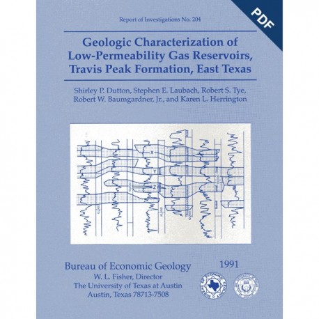
Geologic Characterization of Low-Permeability Gas Reservoirs, Travis Peak Formation, East Texas. Digital Download
RI0204D
For a print version: RI0204.
RI0204D. Geologic Characterization of Low-Permeability Gas Reservoirs, Travis Peak Formation, East Texas, by S. P. Dutton, S. E. Laubach, R. S. Tye, R. W. Baumgardner, Jr., and K. L. Herrington. 84 p., 71 figs., 5 tables, 1991. doi.org/10.23867/RI0204D. Downloadable PDF. To order this publication in book format, please order RI0204.
ABSTRACT
The Lower Cretaceous Travis Peak Formation contains an estimated 6.4 trillion cubic feet (Tcf) of gas in place in East Texas and North Louisiana. Advanced technology will be needed to maximize recovery from this low-permeability ("tight") gas sandstone. This report focuses on the contribution of geology to understanding and efficiently developing the complex gas reservoirs in the Travis Peak Formation in East Texas. Geologic characterization of the Travis Peak Formation included three major areas of study: (1) interpretation of stratigraphy and depositional systems, (2) evaluation of reservoir sandstone diagenesis, and (3) analysis of the structural history and current structural setting.
Depositional systems of the Travis Peak Formation in this region include (1) a braided to meandering fluvial system that composes most of the section, (2) a deltaic system that is interbedded with and encases the distal part of the fluvial system, (3) a paralic system that overlies and interfingers with the deltaic and fluvial systems near the top of the Travis Peak, and (4) a shelf system that is present at the downdip extent of the Travis Peak. Reservoir geometry and quality in the systems vary because of differences in depositional processes that controlled sediment lithology, texture, and stratification, in addition to the degree of diagenesis. Thin sandstones separated by mudstones in the upper part of the formation were deposited in paralic and meandering fluvial environments. Best quality reservoirs in the upper Travis Peak occur in tidal-channel, tidal-flat, and meandering fluvial channel sandstones. In most of the lower part of the Travis Peak, sandstones are dominantly braided fluvial. Best quality reservoirs in the braided fluvial deposits exist in wide channel belts oriented parallel to depositional dip. Reservoir quality decreases at channel margins (levees), at channel tops (abandoned-channel deposits), and in interchannel areas where sediments are poorly sorted.
Petrographic studies indicate that the Travis Peak Formation contains mainly fine- to very fine grained sandstone, muddy sandstone, silty sandstone, and sandy mudstone. True claystones that could provide stress barriers to hydraulic fracture growth are rare. The sandstones are mineralogically mature, consisting of quartzarenites and subarkoses. Well-sorted sandstones had high porosity and permeability at the time of deposition, but their reservoir quality has been reduced by compaction and cementation. Cementation by quartz, dolomite, ankerite, illite, and chlorite and introduction of reservoir bitumen by deasphalting have reduced porosity to less than 8 percent and permeability to less than 0.1 md in much of the formation. Structurally deeper Travis Peak sandstones are more intensely quartz cemented than are shallower sandstones. This variability in cementation results in differences in mechanical properties, porosity, and permeability between upper and lower parts of the Travis Peak. Furthermore, differences in grain size and cementation history of fluvial and paralic sandstones have resulted in fluvial sandstones having an order of magnitude higher permeability than paralic sandstones at all depths.
Because a correspondence exists between extensive quartz cementation and fracture occurrence, abundant, open natural fractures should be expected in highly cemented sandstones. Natural fractures may contribute to production in lower Travis Peak sandstones that have very low matrix permeability. Predicting the propagation direction of hydraulically induced fractures is a key part of completion strategy, and geologic studies of core showed that borehole breakouts and drilling-induced fractures in core can be used as inexpensive and reliable methods of predicting horizontal stress directions and the direction of hydraulic fracture propagation. Hydraulic fractures propagate in directions subparallel to the east-northeast strike of the natural fractures. Thus, hydraulically induced fractures may not intersect many natural fractures. Among the effects that natural fractures can have on well treatments are increased leakoff, fracture branching, and curvature. Branching could cause high treatment pressures and detrimentally affect treatment results if not accounted for in treatment design. Geologic models indicate that natural fractures are not likely to be common in the upper Travis Peak sandstones and that special precautions for treating naturally fractured rock are not required in the upper zone. In the lower Travis Peak, however, natural fractures are common and locally are extensively developed.
Keywords: borehole ellipticity, coring-induced fractures, depositional systems, East Texas, Hosston Formation, microfractures, natural fractures, reservoir quality, sandstone diagenesis, stratigraphy, stress, tight gas sandstones, Travis Peak Formation
CONTENTS
Abstract
Introduction
Geologic Setting
Travis Peak Stratigraphy and Depositional Systems
Methods
Stratigraphy
Depositional Systems
Braided to Meandering Fluvial Depositional System
Fluvial-channel fill
Abandoned-charnel fill
Floodplain
Lacustrine
Overbank
Deltaic Depositional System
Paralic Depositional System
Coastal plain
Marginal marine
Shelf Depositional System
Travis Peak Paleogeographic Evolution
Paleogeography: Time 1
Paleogeography: Time 2
Paleogeography: Time 3
Paleogeography: Time 4
Paleogeography: Time 5
Early Travis Peak Deposition (Times 1-3)
Late Travis Peak Deposition (Times 4-5)
Hydrocarbon Production
Diagenesis
Methods
Travis Peak Composition
Framework Grains
Matrix
Cements
Quartz
Authigenic clay minerals
Carbonate cements
Solid hydrocarbons
Other authigenic minerals
Porosity
Organic Geochemistry
Burial and Thermal History
Diagenetic History
Reservoir Quality
Methods
Porosity Distribution
Permeability Distribution
Controls on Porosity and Permeability
Compaction
Cement
Secondary porosity
Overburden pressure
Depositional environment
Conclusions
Natural Fractures
Methods
Fracture Abundance
Fracture Attitudes
Fracture Morphology and Dimensions
Characterization of Fractures with Borehole-Imaging Logs
Contrasts and Similarities between Travis Peak and Cotton Valley Fractures
Petrology of Travis Peak Fracture-Filling Minerals
Fluid-Inclusion Microthermometry
Relationship between Fracture Development and Diagenesis
Microfractures
Significance of Microfractures.
Interpretations of Fracture Origins
Applications to Reservoir Studies
Stress Directions
Regional Stress Patterns
Borehole Breakouts
Overview
Wellbore Elongation Measurement.
Interpretation of Wellbore Ellipticity
Strain Measurements on Core
Massive Hydraulic Fracture Treatments
Fractures Created in Stress Tests
Drilling-Induced Fractures
Application to Reservoir Development
Engineering Implications
Reservoir Characterization
Reservoir Quality
Structure
Conclusions
Acknowledgments
References
Figures
1. Location of study area and wells
2. Stratigraphic nomenclature, East Texas Basin
3. Structure-contour map, top of Travis Peak Formation
4. Isopach map of Travis Peak Formation in East Texas-West Louisiana study area
5. Location of East Texas counties and West Louisiana parishes included in study of stratigraphy and depositional systems
6. Representative log of Travis Peak Formation from eastern Panola County, Texas
7. Cored intervals plotted by depth below top of Travis Peak
8. Stratigraphic cross section A-A'
9. Stratigraphic cross section B-B'
10. Stratigraphic cross section C-C'
11. Percent-sandstone map, combined lithostratigraphic units 1 through 3
12. Percent-sandstone map, combined lithostratigraphic units 4 and 5
13. Core description of Prairie Mast No. 1-A well, Nacogdoches County, Texas
14. Clay-clast conglomerate developed at base of a fluvial charnel
15. Planar crossbedded fine- to medium-grained fluvial-channel-fill sandstone
16. Small-scale, current-ripple-laminated, fine-grained fluvial-channel-fill sandstone
17. Burrowed, muddy fine-grained abandoned-channel-fill sandstone
18. Densely rooted and burrowed floodplain sandy mudstone
19. Current-ripple-laminated, fine-grained sandstone sharply overlying a laminated and soft-sediment-deformed sandy mudstone
20. Slumped muddy fine-grained sandstone deposited in an overbank environment (levee or splay)
21. Wavy- and lenticular-bedded muddy fine-grained sandstone deposited in a lake or bay
22. Burrowed to bioturbated, wavy-bedded and ripple-laminated muddy sandstone
23. Core description of Clayton Williams Sam Hughes No. 1 well, Panola County, Texas
24. Hypothetical paleogeographic reconstructions of five time periods during Travis Peak deposition
25. Structure-contour map, top of Cotton Valley Formation, North Appleby field
26. Gamma-ray and resistivity logs and informal nomenclature, Travis Peak Formation, SFE No. 2 well, North Appleby field
27. Stratigraphic cross section D-D' illustrating the occurrence and geometry of channel-belt sandstones in lower Travis Peak, core zone 4, North Appleby field
28. Net-sandstone and log-pattern map, Sandstone X, lower Travis Peak, core zone 4, North Appleby field
29. Stratigraphic cross section D-D' illustrating the occurrence and geometry of channel-belt sandstones in upper Travis Peak, core zone 1, North Appleby field
30. Net-sandstone map, Sandstone B, upper Travis Peak, core zone 1, North Appleby field
31. Photomicrograph of quartz cement in a clean Travis Peak sandstone
32. Moderate amount of quartz cement in a sample that retains primary porosity
33. Quartz cement volume in clean sandstones as a function of present burial depth
34. SEM photograph of fibrous illite filling a secondary pore formed by the dissolution of a feldspar grain
35. SEM photograph of a rosette of authigenic chlorite from a depth of 7,383.6 ft (2.250.5 m) Mobil Cargill No. 15 well
36. SEM photograph of fibrous illite in a sample that was freeze dried to preserve the original morphology of the long, delicate fibers
37. SEM photograph of matted illite fibers in an extraction-dried sample taken immediately adjacent to the sample shown in figure 36
38. Rippled sandstone with reservoir bitumen highlighting ripple faces, from a depth of 8,240.0 ft (2,511.6 m), Stallworth Everett No. 2-B core
39. Plot of reservoir bitumen volume with depth below top of Travis Peak
40, Photomicrograph of reservoir bitumen in primary porosity at a depth of 8,386.7 ft (2,556.3 m), ARCO Phillips No. 1 core
41. Burial-history curves, tops of Travis Peak Formation, Cotton Valley Group, Bossier Shale, and Smackover Formation. Ashland SFOT No. 1 and Sun D. O. Caudle No. 2wells
42. Burial-history curve, Ashland SFOT No. 1 well, showing when major diagenetic events may have occurred
43. Plot of porosimeter porosity versus depth for 1. 687 Travis Peak sandstones
44. Plot of porosimeter porosity versus depth for 89 clean Travis Peak sandstones
45. Plot of secondary porosity measured in thin section versus depth in clean fluvial sandstones
46. Plot of stressed permeability versus depth for 649 Travis Peak sandstones
47. Plot of stressed permeability versus depth for 66 clean Travis Peak sandstones
48. Plot of unstressed permeability versus depth for 176 clean Travis Peak sandstones
49. Plot of porosimeter porosity versus stressed permeability for 649 Travis Peak sandstones
50. Comparison of sandstones from similar depositional environments at different present burial depths
51. Inverse relationship between total cement volume and unstressed permeability in clean sandstones
52. Inverse relationship between quartz cement volume and unstressed permeability in clean sandstones
53. Total cement volume in clean sandstones as a function of present burial depth
54. Core gamma-ray log, core profile, fracture distribution, and environmental interpretation, cores 1 through 3, Holditch SFE No. 2 well
55. Core gamma-ray log, core profile, fracture distribution, and environmental interpretation, cores 9 through 15, Holditch SFE No. 2 well
56. Strikes of natural fractures in Travis Peak sandstones
57. Two views of an open fracture in the Holditch SEE No. 2 core, from a depth of 9,842 ft (3,000 m)
58. Fractures in reservoir rocks imaged with Formation Microscanner and borehole televiewer logs
59. Photomicrograph showing superposition of infilling mineral phases in Travis Peak fracture
60. Photomicrographs of fluid inclusions in Travis Peak quartz-filled fractures
61. Homogenization temperatures from vein quartz and calcite
62. Homogenization temperature versus salinity and final melting temperature
63. Preferred orientation of closed microfractures in a single well
64. Sketch of a hydraulic fracture induced by open-hole stress test 2, Holditch SFE No. 2 well
65. Box plots of stress-direction indicators. Travis Peak Formation
66. Stress-direction indicators, Holditch Howell No. 5 well, drilling-induced fractures in the same core interval, and stereographic projection of fractures created during hydraulic fracture treatment
67. Map of seven wells with polar plots of H for wellbore ellipticity
68. Plan views and sections of ellipticity logs for in-gauge borehole, borehole breakout, and washout
69. Plot of wells showing intervals in Travis Peak Formation covered by ellipticity logs in this study
70. Plots of ellipticity ratio versus depth below Kelly bushing
71. Plots of ellipticity ratio versus elevation relative to top of Travis Peak Formation
Tables
1. Travis Peak cores used in this study
2. Linear regression correlation coefficients between log stressed permeability and various textural and mineralogic parameters in 66 clean Travis Peak sandstones
3. Distribution of average porosity and permeability by sedimentary structure
4. Differences in coring-induced and natural fracture strike in continuous core intervals
5. Isotopic composition of vein quartz and vein carbonate
Citation
Dutton, S. P., Laubach, S. E., Tye, R. S., Baumgardner, R. W., Jr., and Herrington, K. L., 1991, Geologic Characterization of Low-Permeability Gas Reservoirs, Travis Peak Formation, East Texas: The University of Texas at Austin, Bureau of Economic Geology, Report of Investigations No. 204, 84 p.
